INTRODUCTION
Years back man believed that life exist only in earth and he was totally ignorant about the world beyond it. But man’s quest for knowledge didn’t limit him. For reaching out to the far space he made use of technology and through years of research and hard work he found an alternative, a substitute for him and evolved robots.
Robotics has developed much since its evolution. Be it space exploration or in engineering expeditions robots are in the forefront helping mankind .Most common feature in all these applications is direction finding. It was in March 1997, NASA landed a single vehicle with micro rover, named Sojourner to explore the red planet, Mars. The Mars pathfinder investigated surface of mars with three additional science instruments which allowed investigation of geology, surface morphology, geochemistry and petrology of rocks. It allowed a first order scientific investigation of early differentiation and evolution of crust, development of weather and early environment that have existed on Mars.
Getting inspiration from this pathfinder we have developed our own model of pathfinder in miniature form of the original. Our aim is to build an autonomous maze solving robot that can be used as a pathfinder to remote and unhampered regions inaccessible to human beings.
The design of the robot consists of the study of various electromechanical aspects.
Block Diagram
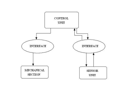
The different sections of the robot are
· Sensor section
· Mechanical section
· Control unit

MICROCONTROLLER
The microcontroller is the brain of the robot which controls the operation of the robot. Microcontroller is a device which includes a microprocessor, memory and IO lines on a single chip fabricated using VLSI technology. The assembly language programs written in the microcontroller receives input data, manipulates it, and provides necessary control signals to the hardware. The microcontroller we are using is AT 89C51. The main features of AT89C51 are
1. 4 KB of in system reprogrammable memory.
2. 128 B of internal RAM.
3. 32 bit programmable I/O RAM.
4. Two16-bit timer/counter.
STEPPER MOTOR
A stepper motor is a brush less DC motor whose rotor rotates in discrete angular increments when its stator windings are energized in a programmed manner. Rotation occurs because of magnetic interaction between rotor poles and poles of the sequentially energized stator windings. The rotor has no electrical windings, but has silent and magnetized poles.
SENSOR
The sensor is meant to find the obstacles and difficulties in the path of the robot. Utilizing the reflective properties of the Infra Red rays the sensor part will detect the obstacles in the path of the robot. The obstacles sensor is mounted on a sensor stepper motor which helps the rays to scan to the left and right sides of the robot.
A pit sensor is also incorporated in the robot to avoid risk of robot falling into pits. This level sensor makes this robot more intelligent. Pit sensor is just a mechanical contact placed in front of the two front wheels.
POWER SUPPLY
Power supply section of the robot consists of a bridge rectifier, filter, and various regulator ICs for charging the battery and for providing power for the various ICs in the circuit and also for stepper motor and dc motors.
CIRCUIT DIAGRAM
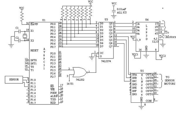
The detailed circuit diagram of path finder robot is shown above. It mainly consists of the powerful microcontroller AT89C51, input sensors, latch, stepper motor and DC motor driver. The controller is the main part of our system, which controls all the operations of the robot.
An IR led connected at the front end emits IR energy. An IR sensor is also placed near the IR LED such that the direct radiation from the LED never hits the receiver. If any obstacle comes in front of the vehicle the IR energy radiated from the IR led gets reflected back from the obstacle. This reflected energy from the obstacle is received by the IR receiver and produces a square waveform at its output. This signal is fed to the controllers P1.0 pin.
In our system we use two dc motors as the wheel motors and one stepper motor as sensor motor. The output data for the DC motors from the controller is fed to the dc motors through a dc motor driver. We are using L293D as dc motor driver. The data for the stepper motor from the controller is fed to the stepper through the stepper motor driver. We are using ULN 2004 as the stepper motor driver. The four coils of the stepper are connected to the stepper driver. The common point of the stepper is connected to +12V. ULN 2004 contains high current high voltage
We are using 74LS374 as latches in our system. We are using latches in our system our store the data for stepper and DC motor.
SENSOR
Sensor circuit consists of an IR transmitter and receiver. The reflective property of the IR is used for finding the obstacles. Whenever a signal is received from the obstacle the sensor mounted stepper motor turns to the left side to scan whether there is any obstacle in the left side of the vehicle. And the motor turns back the original position. It remains in the original position if there no obstacle sensed in the left side. If an obstacle is sensed in the left side then the motor will turn the right side to scan for obstacles in the right side of the vehicle. After scanning the sensor comes back to the original position.
The pit sensor is permanently grounded. The output of the pit sensor is connected o the input port pins (P1.1, P1.2) of the microcontroller. The level sensor in the right side is connected to the pin P1.1. The left side level sensor is connected to the P1.2. The P1.1 and P1.2 pins permanently get an active high signal. When a physical contact is made the port pins get an active low signal. This will set a bit in the program. And according to the program the vehicle moves back and then moves to left or right. If the active low signal is in the P1.2 the vehicle moves to right after the reverse movement.